
Tank Wind Load#
|
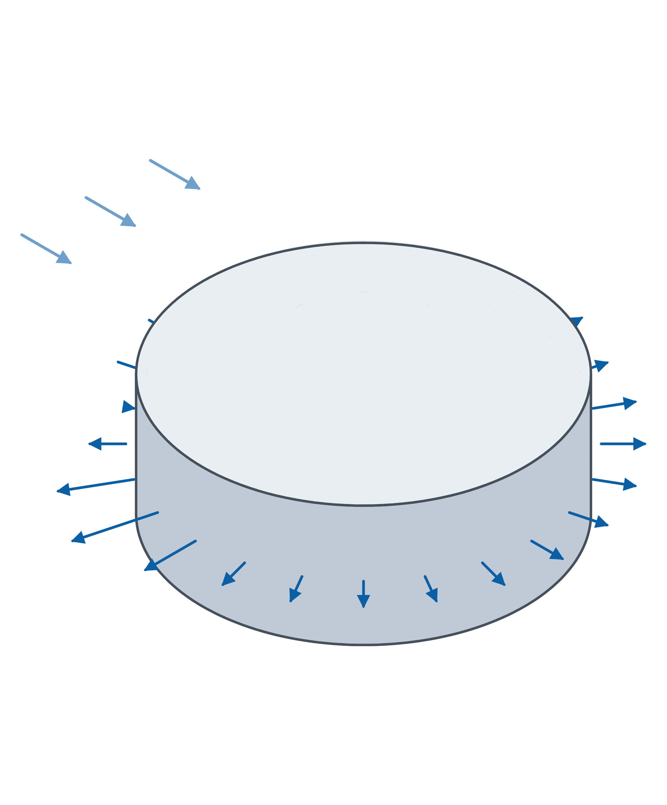
Modelling a cylindrical tank and loading it with wind to EN 1991-1-4, clause 7.9:
Keywords:
tank rotated surface arc line circle line line support free rectangular load varying along perimeter wind load EN 1991-1-4 support reactions |
from dlubal.api import rfem
from math import inf, pi, log, sqrt, cos, radians

# -------------------------------------------------------
# This example demonstrates how to model a cylindrical tank
# and load it with wind to EN 1991-1-4, clause 7.9. The
# shell and its domed roof are each generated by rotating a
# single boundary line about the vertical axis.
#
# The external pressure coefficient round the perimeter
# follows Figure 7.27: a c_p0 curve selected by Reynolds
# number, scaled by the end-effect factor, and handed over
# as a free rectangular load varying along the perimeter.
#
# The base shear is then read back from the support and
# checked against the pressure integrated round the
# perimeter, so the example proves its own loading.
# -------------------------------------------------------

# Editable parameters (SI units)
MODEL_NAME = "tank_wind_load"

TANK_RADIUS = 4.0                  # r [m]
WALL_HEIGHT = 3.0                  # eaves above the base [m]
APEX_HEIGHT = 3.6                  # roof apex above the base [m]
SHELL_THICKNESS = 0.010            # [m]
MATERIAL = "S355"

BASIC_WIND_VELOCITY = 20.0         # v_b [m/s]
ROUGHNESS_LENGTH = 0.20            # z_0 [m], terrain category III
ROUGHNESS_LENGTH_II = 0.05         # z_0,II [m], the reference terrain
AIR_DENSITY = 1.25                 # rho [kg/m3]
KINEMATIC_VISCOSITY = 15e-6        # nu [m2/s]
AXIS_START_ANGLE = pi              # where alpha = 0 sits on the tank [rad]

# Figure 7.27: c_p0 round the perimeter at three Reynolds numbers, with the
# angles at which the end-effect factor starts and reaches its full value.
ANGLES = list(range(0, 361, 15))
REYNOLDS = [5e5, 2e6, 1e7]
ALPHA_MIN = [85.0, 80.0, 75.0]
ALPHA_A = [135.0, 120.0, 105.0]
CP0 = [
    [1.0, 0.7, 0.1, -0.65, -1.45, -1.97, -2.15, -1.95, -1.25, -0.40, -0.40, -0.40, -0.40,
     -0.40, -0.40, -0.40, -1.25, -1.95, -2.15, -1.97, -1.45, -0.65, 0.1, 0.7, 1.0],
    [1.0, 0.7, 0.1, -0.60, -1.35, -1.76, -1.73, -1.40, -0.70, -0.70, -0.70, -0.70, -0.70,
     -0.70, -0.70, -0.70, -0.70, -1.40, -1.73, -1.76, -1.35, -0.60, 0.1, 0.7, 1.0],
    [1.0, 0.7, 0.1, -0.55, -1.20, -1.50, -1.30, -0.80, -0.80, -0.80, -0.80, -0.80, -0.80,
     -0.80, -0.80, -0.80, -0.80, -0.80, -1.30, -1.50, -1.20, -0.55, 0.1, 0.7, 1.0],
]


def peak_velocity_pressure(height) -> float:
    """Return q_p(z) to EN 1991-1-4 4.5, for orography factor c_o = 1."""

    terrain_factor = 0.19 * (ROUGHNESS_LENGTH / ROUGHNESS_LENGTH_II) ** 0.07
    mean_velocity = BASIC_WIND_VELOCITY * terrain_factor * log(height / ROUGHNESS_LENGTH)
    turbulence_intensity = 1.0 / log(height / ROUGHNESS_LENGTH)
    return (1 + 7 * turbulence_intensity) * 0.5 * AIR_DENSITY * mean_velocity ** 2


def end_effect_factor(alpha, alpha_min, alpha_a, psi_lambda) -> float:
    """Return psi_lambda_alpha to EN 1991-1-4 7.9.

    Full value up to alpha_min, a cosine transition to alpha_A, then the
    slenderness factor. The first test has to include alpha = 0: that is the
    stagnation point, and a strict > drops it into the transition branch and
    returns roughly 0.71 where the answer is 1.0.
    """

    if alpha <= alpha_min:
        return 1.0
    if alpha < alpha_a:
        return psi_lambda + (1 - psi_lambda) * cos(
            pi / 2 * (alpha - alpha_min) / (alpha_a - alpha_min))
    return psi_lambda


def interpolate_on_reynolds(reynolds) -> tuple:
    """Return the c_p0 curve and its transition angles at this Reynolds number."""

    if reynolds <= REYNOLDS[0]:
        return CP0[0], ALPHA_MIN[0], ALPHA_A[0]
    if reynolds >= REYNOLDS[2]:
        return CP0[2], ALPHA_MIN[2], ALPHA_A[2]
    lower = 0 if reynolds <= REYNOLDS[1] else 1
    span = (reynolds - REYNOLDS[lower]) / (REYNOLDS[lower + 1] - REYNOLDS[lower])
    blend = [a + (b - a) * span for a, b in zip(CP0[lower], CP0[lower + 1])]
    return (blend,
            ALPHA_MIN[lower] + (ALPHA_MIN[lower + 1] - ALPHA_MIN[lower]) * span,
            ALPHA_A[lower] + (ALPHA_A[lower + 1] - ALPHA_A[lower]) * span)


def external_pressure_coefficients() -> tuple:
    """Return q_p and the c_pe round the perimeter, one per entry in ANGLES."""

    q_p = peak_velocity_pressure(APEX_HEIGHT)

    # Reynolds number to eq. 7.15: the DIAMETER, and the peak wind velocity,
    # which is the velocity equivalent of q_p rather than the basic velocity.
    peak_velocity = sqrt(2 * q_p / AIR_DENSITY)
    reynolds = 2 * TANK_RADIUS * peak_velocity / KINEMATIC_VISCOSITY

    slenderness = APEX_HEIGHT / (2 * TANK_RADIUS)
    psi_lambda = 1 / (1 + slenderness ** 2)

    cp0, alpha_min, alpha_a = interpolate_on_reynolds(reynolds)
    cpe = [c * end_effect_factor(a, alpha_min, alpha_a, psi_lambda)
           for a, c in zip(ANGLES, cp0)]

    print(f"\nWind to EN 1991-1-4 7.9:")
    print(f"  q_p = {q_p:.1f} Pa, v(z_e) = {peak_velocity:.2f} m/s, Re = {reynolds:.3e}")
    print(f"  alpha_min = {alpha_min:.1f} deg, alpha_A = {alpha_a:.1f} deg, "
          f"psi_lambda = {psi_lambda:.4f}")
    print(f"  c_pe from {min(cpe):.3f} to {max(cpe):.3f}")
    return q_p, cpe


def base_shear_from_pressure(q_p, cpe) -> float:
    """Integrate the wind pressure round the perimeter into a base shear.

    The pressure acts radially, so only its component along the wind survives;
    AXIS_START_ANGLE turns the whole distribution and so decides the sign.
    """

    total = 0.0
    for i in range(len(ANGLES) - 1):
        step = radians(ANGLES[i + 1] - ANGLES[i])
        mean = (cpe[i] * cos(radians(ANGLES[i]) + AXIS_START_ANGLE)
                + cpe[i + 1] * cos(radians(ANGLES[i + 1]) + AXIS_START_ANGLE)) / 2
        total += mean * step
    return total * q_p * TANK_RADIUS * WALL_HEIGHT


def define_structure() -> list:
    """Define and return a list of structural objects."""

    return [
        rfem.structure_core.Material(no=1, name=MATERIAL),
        rfem.structure_core.Thickness(no=1, uniform_thickness=SHELL_THICKNESS, material=1),

        # Only the generating profile is given: a vertical line up the wall and
        # an arc from the eaves to the apex. Each is swept into a surface below.
        rfem.structure_core.Node(no=2, coordinate_1=-TANK_RADIUS, coordinate_2=0, coordinate_3=0),
        rfem.structure_core.Node(no=3, coordinate_1=-TANK_RADIUS, coordinate_2=0, coordinate_3=-WALL_HEIGHT),
        rfem.structure_core.Node(no=10, coordinate_1=0, coordinate_2=0, coordinate_3=-APEX_HEIGHT),

        rfem.structure_core.Line(no=2, definition_nodes=[2, 3]),
        rfem.structure_core.Line(
            no=3, type=rfem.structure_core.Line.TYPE_ARC,
            arc_first_node=3, arc_second_node=10,
            arc_control_point_x=-2.022, arc_control_point_y=0, arc_control_point_z=-3.449,
            arc_center_x=0, arc_center_y=0, arc_center_z=10.033,
            arc_height=0.151, arc_radius=13.633, arc_alpha=0.2977533),

        # The eaves and base rings. The base ring carries the support.
        rfem.structure_core.Line(
            no=4, type=rfem.structure_core.Line.TYPE_CIRCLE,
            circle_center_coordinate_1=0, circle_center_coordinate_2=0,
            circle_center_coordinate_3=-WALL_HEIGHT,
            circle_radius=TANK_RADIUS, circle_rotation=pi,
            circle_normal_coordinate_1=0, circle_normal_coordinate_2=0,
            circle_normal_coordinate_3=1),
        rfem.structure_core.Line(
            no=5, type=rfem.structure_core.Line.TYPE_CIRCLE,
            circle_center_coordinate_1=0, circle_center_coordinate_2=0,
            circle_center_coordinate_3=0,
            circle_radius=TANK_RADIUS, circle_rotation=pi,
            circle_normal_coordinate_1=0, circle_normal_coordinate_2=0,
            circle_normal_coordinate_3=1),

        rfem.structure_core.Surface(
            no=1, geometry=rfem.structure_core.Surface.GEOMETRY_ROTATED,
            rotated_boundary_line=3, rotated_angle_of_rotation=2 * pi,
            thickness=1, material=1),
        rfem.structure_core.Surface(
            no=2, geometry=rfem.structure_core.Surface.GEOMETRY_ROTATED,
            rotated_boundary_line=2, rotated_angle_of_rotation=2 * pi,
            thickness=1, material=1),

        rfem.types_for_lines.LineSupport(
            no=1, lines=[5], spring_x=inf, spring_y=inf, spring_z=inf),
    ]


def define_loading(q_p, cpe) -> list:
    """Define and return a list of loading objects."""

    # recalculated_magnitude is deliberately NOT set on the rows. RFEM derives
    # it from magnitude_uniform x factor, and supplying it drives the factor the
    # other way: passing the same value on every row - easy to do, since it
    # looks like the reference pressure - makes every factor come back as 1.0
    # and throws the whole distribution away.
    rows = [
        rfem.loads.FreeRectangularLoad.LoadVaryingAlongPerimeterParametersRow(
            no=i + 1,
            description="",
            alpha=radians(alpha),
            factor=factor,
            note="")
        for i, (alpha, factor) in enumerate(zip(ANGLES, cpe))
    ]

    return [
        rfem.loading.StaticAnalysisSettings(
            no=1,
            analysis_type=rfem.loading.StaticAnalysisSettings.ANALYSIS_TYPE_GEOMETRICALLY_LINEAR),

        rfem.loading.LoadCase(
            no=1,
            name="Wind",
            analysis_type=rfem.loading.LoadCase.ANALYSIS_TYPE_STATIC_ANALYSIS,
            action_category=rfem.loading.LoadCase.ACTION_CATEGORY_WIND_QW,
            static_analysis_settings=1,
            self_weight_active=False),

        # Applied to the shell only. Figure 7.27 covers the cylinder; the roof
        # takes its coefficients from a different clause.
        rfem.loads.FreeRectangularLoad(
            no=1, surfaces=[2], load_case=1,
            load_distribution=rfem.loads.FreeRectangularLoad.LOAD_DISTRIBUTION_VARYING_ALONG_PERIMETER,
            load_direction=rfem.loads.FreeRectangularLoad.LOAD_DIRECTION_LOCAL_Z,
            load_projection=rfem.loads.FreeRectangularLoad.LOAD_PROJECTION_XY_OR_UV,
            load_location_rectangle=rfem.loads.FreeRectangularLoad.LOAD_LOCATION_RECTANGLE_CENTER_AND_SIDES,
            load_location_center_coordinate_1=0,
            load_location_center_coordinate_2=0,
            load_location_center_side_a=4 * TANK_RADIUS,
            load_location_center_side_b=4 * TANK_RADIUS,
            axis_start_angle=AXIS_START_ANGLE,
            magnitude_uniform=q_p,
            axis_definition_p1={'x': 0, 'y': 0, 'z': 0},
            axis_definition_p2={'x': 0, 'y': 0, 'z': -1},
            load_varying_along_perimeter_parameters=(
                rfem.loads.FreeRectangularLoad.LoadVaryingAlongPerimeterParametersTable(rows=rows))),
    ]


# Connect to the RFEM application
with rfem.Application() as rfem_app:

    app_info = rfem_app.get_application_info()
    print(f"\nApplication Info:\n{app_info}")

    q_p, cpe = external_pressure_coefficients()

    # Modelling
    rfem_app.close_all_models(save_changes=False)
    rfem_app.create_model(name=MODEL_NAME)
    rfem_app.delete_all_objects()
    rfem_app.create_object_list(define_structure() + define_loading(q_p, cpe))

    # Calculation
    calculation_info = rfem_app.calculate_all(
        skip_warnings=True
    )
    print(f"\nCalculation Info:\n{calculation_info}")

    # Results
    # p_x is a DISTRIBUTED reaction in N/m sampled along the support line, not a
    # force, so it is integrated over location_x. Summing the column instead
    # gives a number that depends only on how finely the line was meshed.
    support_forces_df = rfem_app.get_results(
        results_type=rfem.results.STATIC_ANALYSIS_LINES_SUPPORT_FORCES
    ).data.sort_values("location_x")

    arc = support_forces_df["location_x"].astype(float).tolist()
    intensity = support_forces_df["p_x"].astype(float).tolist()
    base_shear = sum((intensity[i] + intensity[i + 1]) / 2 * (arc[i + 1] - arc[i])
                     for i in range(len(arc) - 1))
    expected = base_shear_from_pressure(q_p, cpe)

    print(f"\nBase shear along the wind:")
    print(f"  from the support reaction:  {base_shear:.1f} N")
    print(f"  from the pressure, by hand: {expected:.1f} N")
    print(f"  difference:                 {abs(base_shear - expected) / abs(expected):.2%}")
using Rfem = Dlubal.Api.Rfem;
using Google.Protobuf;

// -------------------------------------------------------
// This example demonstrates how to model a cylindrical tank
// and load it with wind to EN 1991-1-4, clause 7.9. The
// shell and its domed roof are each generated by rotating a
// single boundary line about the vertical axis.
//
// The external pressure coefficient round the perimeter
// follows Figure 7.27: a c_p0 curve selected by Reynolds
// number, scaled by the end-effect factor, and handed over
// as a free rectangular load varying along the perimeter.
//
// The base shear is then read back from the support and
// checked against the pressure integrated round the
// perimeter, so the example proves its own loading.
// -------------------------------------------------------

// Editable parameters (SI units)
const string MODEL_NAME = "tank_wind_load";

const double TANK_RADIUS = 4.0;              // r [m]
const double WALL_HEIGHT = 3.0;              // eaves above the base [m]
const double APEX_HEIGHT = 3.6;              // roof apex above the base [m]
const double SHELL_THICKNESS = 0.010;        // [m]
const string MATERIAL = "S355";

const double BASIC_WIND_VELOCITY = 20.0;     // v_b [m/s]
const double ROUGHNESS_LENGTH = 0.20;        // z_0 [m], terrain category III
const double ROUGHNESS_LENGTH_II = 0.05;     // z_0,II [m], the reference terrain
const double AIR_DENSITY = 1.25;             // rho [kg/m3]
const double KINEMATIC_VISCOSITY = 15e-6;    // nu [m2/s]
const double AXIS_START_ANGLE = Math.PI;   // where alpha = 0 sits [rad]

// Figure 7.27: c_p0 round the perimeter at three Reynolds numbers, with the
// angles at which the end-effect factor starts and reaches its full value.
int[] ANGLES = Enumerable.Range(0, 25).Select(i => i * 15).ToArray();
double[] REYNOLDS = { 5e5, 2e6, 1e7 };
double[] ALPHA_MIN = { 85.0, 80.0, 75.0 };
double[] ALPHA_A = { 135.0, 120.0, 105.0 };
double[][] CP0 = {
    new[] { 1.0, 0.7, 0.1, -0.65, -1.45, -1.97, -2.15, -1.95, -1.25, -0.40, -0.40, -0.40, -0.40,
            -0.40, -0.40, -0.40, -1.25, -1.95, -2.15, -1.97, -1.45, -0.65, 0.1, 0.7, 1.0 },
    new[] { 1.0, 0.7, 0.1, -0.60, -1.35, -1.76, -1.73, -1.40, -0.70, -0.70, -0.70, -0.70, -0.70,
            -0.70, -0.70, -0.70, -0.70, -1.40, -1.73, -1.76, -1.35, -0.60, 0.1, 0.7, 1.0 },
    new[] { 1.0, 0.7, 0.1, -0.55, -1.20, -1.50, -1.30, -0.80, -0.80, -0.80, -0.80, -0.80, -0.80,
            -0.80, -0.80, -0.80, -0.80, -0.80, -1.30, -1.50, -1.20, -0.55, 0.1, 0.7, 1.0 },
};

// Returns q_p(z) to EN 1991-1-4 4.5, for orography factor c_o = 1.
double PeakVelocityPressure(double height)
{
    double terrainFactor = 0.19 * Math.Pow(ROUGHNESS_LENGTH / ROUGHNESS_LENGTH_II, 0.07);
    double meanVelocity = BASIC_WIND_VELOCITY * terrainFactor * Math.Log(height / ROUGHNESS_LENGTH);
    double turbulenceIntensity = 1.0 / Math.Log(height / ROUGHNESS_LENGTH);
    return (1 + 7 * turbulenceIntensity) * 0.5 * AIR_DENSITY * meanVelocity * meanVelocity;
}

// Returns psi_lambda_alpha to EN 1991-1-4 7.9. Full value up to alphaMin, a
// cosine transition to alphaA, then the slenderness factor. The first test has
// to include alpha = 0: that is the stagnation point, and a strict > drops it
// into the transition branch and returns roughly 0.71 where the answer is 1.0.
double EndEffectFactor(double alpha, double alphaMin, double alphaA, double psiLambda)
{
    if (alpha <= alphaMin) return 1.0;
    if (alpha < alphaA)
        return psiLambda + (1 - psiLambda) * Math.Cos(
            Math.PI / 2 * (alpha - alphaMin) / (alphaA - alphaMin));
    return psiLambda;
}

// Returns the c_p0 curve and its transition angles at this Reynolds number.
(double[] Cp0, double AlphaMin, double AlphaA) InterpolateOnReynolds(double reynolds)
{
    if (reynolds <= REYNOLDS[0]) return (CP0[0], ALPHA_MIN[0], ALPHA_A[0]);
    if (reynolds >= REYNOLDS[2]) return (CP0[2], ALPHA_MIN[2], ALPHA_A[2]);
    int lower = reynolds <= REYNOLDS[1] ? 0 : 1;
    double span = (reynolds - REYNOLDS[lower]) / (REYNOLDS[lower + 1] - REYNOLDS[lower]);
    var blend = CP0[lower].Zip(CP0[lower + 1], (a, b) => a + (b - a) * span).ToArray();
    return (blend,
            ALPHA_MIN[lower] + (ALPHA_MIN[lower + 1] - ALPHA_MIN[lower]) * span,
            ALPHA_A[lower] + (ALPHA_A[lower + 1] - ALPHA_A[lower]) * span);
}

// Returns q_p and the c_pe round the perimeter, one per entry in ANGLES.
(double QP, double[] Cpe) ExternalPressureCoefficients()
{
    double qP = PeakVelocityPressure(APEX_HEIGHT);

    // Reynolds number to eq. 7.15: the DIAMETER, and the peak wind velocity,
    // which is the velocity equivalent of q_p rather than the basic velocity.
    double peakVelocity = Math.Sqrt(2 * qP / AIR_DENSITY);
    double reynolds = 2 * TANK_RADIUS * peakVelocity / KINEMATIC_VISCOSITY;

    double slenderness = APEX_HEIGHT / (2 * TANK_RADIUS);
    double psiLambda = 1 / (1 + slenderness * slenderness);

    var (cp0, alphaMin, alphaA) = InterpolateOnReynolds(reynolds);
    var cpe = ANGLES.Select((a, i) => cp0[i] * EndEffectFactor(a, alphaMin, alphaA, psiLambda)).ToArray();

    Console.WriteLine("\nWind to EN 1991-1-4 7.9:");
    Console.WriteLine($"  q_p = {qP:F1} Pa, v(z_e) = {peakVelocity:F2} m/s, Re = {reynolds:E3}");
    Console.WriteLine($"  alpha_min = {alphaMin:F1} deg, alpha_A = {alphaA:F1} deg, psi_lambda = {psiLambda:F4}");
    Console.WriteLine($"  c_pe from {cpe.Min():F3} to {cpe.Max():F3}");
    return (qP, cpe);
}

// Integrates the wind pressure round the perimeter into a base shear. The
// pressure acts radially, so only its component along the wind survives;
// AXIS_START_ANGLE turns the whole distribution and so decides the sign.
double BaseShearFromPressure(double qP, double[] cpe)
{
    double total = 0.0;
    for (int i = 0; i < ANGLES.Length - 1; i++)
    {
        double step = (ANGLES[i + 1] - ANGLES[i]) * Math.PI / 180.0;
        double mean = (cpe[i] * Math.Cos(ANGLES[i] * Math.PI / 180.0 + AXIS_START_ANGLE)
                     + cpe[i + 1] * Math.Cos(ANGLES[i + 1] * Math.PI / 180.0 + AXIS_START_ANGLE)) / 2;
        total += mean * step;
    }
    return total * qP * TANK_RADIUS * WALL_HEIGHT;
}

// Returns a list of structural objects to be created.
List<IMessage> DefineStructure()
{
    double inf = double.PositiveInfinity;
    return new List<IMessage>
    {
        new Rfem.StructureCore.Material { No = 1, Name = MATERIAL },
        new Rfem.StructureCore.Thickness { No = 1, UniformThickness = SHELL_THICKNESS, Material = 1 },

        // Only the generating profile is given: a vertical line up the wall and
        // an arc from the eaves to the apex. Each is swept into a surface below.
        new Rfem.StructureCore.Node { No = 2, Coordinate1 = -TANK_RADIUS, Coordinate2 = 0, Coordinate3 = 0 },
        new Rfem.StructureCore.Node { No = 3, Coordinate1 = -TANK_RADIUS, Coordinate2 = 0, Coordinate3 = -WALL_HEIGHT },
        new Rfem.StructureCore.Node { No = 10, Coordinate1 = 0, Coordinate2 = 0, Coordinate3 = -APEX_HEIGHT },

        new Rfem.StructureCore.Line { No = 2, DefinitionNodes = { 2, 3 } },
        new Rfem.StructureCore.Line {
            No = 3, Type = Rfem.StructureCore.Line.Types.Type.Arc,
            ArcFirstNode = 3, ArcSecondNode = 10,
            ArcControlPointX = -2.022, ArcControlPointY = 0, ArcControlPointZ = -3.449,
            ArcCenterX = 0, ArcCenterY = 0, ArcCenterZ = 10.033,
            ArcHeight = 0.151, ArcRadius = 13.633, ArcAlpha = 0.2977533 },

        // The eaves and base rings. The base ring carries the support.
        new Rfem.StructureCore.Line {
            No = 4, Type = Rfem.StructureCore.Line.Types.Type.Circle,
            CircleCenterCoordinate1 = 0, CircleCenterCoordinate2 = 0,
            CircleCenterCoordinate3 = -WALL_HEIGHT,
            CircleRadius = TANK_RADIUS, CircleRotation = Math.PI,
            CircleNormalCoordinate1 = 0, CircleNormalCoordinate2 = 0, CircleNormalCoordinate3 = 1 },
        new Rfem.StructureCore.Line {
            No = 5, Type = Rfem.StructureCore.Line.Types.Type.Circle,
            CircleCenterCoordinate1 = 0, CircleCenterCoordinate2 = 0,
            CircleCenterCoordinate3 = 0,
            CircleRadius = TANK_RADIUS, CircleRotation = Math.PI,
            CircleNormalCoordinate1 = 0, CircleNormalCoordinate2 = 0, CircleNormalCoordinate3 = 1 },

        new Rfem.StructureCore.Surface {
            No = 1, Geometry = Rfem.StructureCore.Surface.Types.Geometry.Rotated,
            RotatedBoundaryLine = 3, RotatedAngleOfRotation = 2 * Math.PI,
            Thickness = 1, Material = 1 },
        new Rfem.StructureCore.Surface {
            No = 2, Geometry = Rfem.StructureCore.Surface.Types.Geometry.Rotated,
            RotatedBoundaryLine = 2, RotatedAngleOfRotation = 2 * Math.PI,
            Thickness = 1, Material = 1 },

        new Rfem.TypesForLines.LineSupport {
            No = 1, Lines = { 5 }, SpringX = inf, SpringY = inf, SpringZ = inf },
    };
}

// Returns a list of loading objects to be created.
List<IMessage> DefineLoading(double qP, double[] cpe)
{
    // RecalculatedMagnitude is deliberately NOT set on the rows. RFEM derives
    // it from MagnitudeUniform x Factor, and supplying it drives the factor the
    // other way: passing the same value on every row - easy to do, since it
    // looks like the reference pressure - makes every factor come back as 1.0
    // and throws the whole distribution away.
    var rows = new List<Rfem.Loads.FreeRectangularLoad.Types.LoadVaryingAlongPerimeterParametersRow>();
    for (int i = 0; i < ANGLES.Length; i++)
    {
        rows.Add(new Rfem.Loads.FreeRectangularLoad.Types.LoadVaryingAlongPerimeterParametersRow
        {
            No = i + 1,
            Description = "",
            Alpha = ANGLES[i] * Math.PI / 180.0,
            Factor = cpe[i],
            Note = "",
        });
    }

    return new List<IMessage>
    {
        new Rfem.Loading.StaticAnalysisSettings {
            No = 1,
            AnalysisType = Rfem.Loading.StaticAnalysisSettings.Types.AnalysisType.GeometricallyLinear },

        new Rfem.Loading.LoadCase {
            No = 1,
            Name = "Wind",
            AnalysisType = Rfem.Loading.LoadCase.Types.AnalysisType.StaticAnalysis,
            ActionCategory = Rfem.Loading.LoadCase.Types.ActionCategory.WindQw,
            StaticAnalysisSettings = 1,
            SelfWeightActive = false },

        // Applied to the shell only. Figure 7.27 covers the cylinder; the roof
        // takes its coefficients from a different clause.
        new Rfem.Loads.FreeRectangularLoad {
            No = 1, Surfaces = { 2 }, LoadCase = 1,
            LoadDistribution = Rfem.Loads.FreeRectangularLoad.Types.LoadDistribution.VaryingAlongPerimeter,
            LoadDirection = Rfem.Loads.FreeRectangularLoad.Types.LoadDirection.LocalZ,
            LoadProjection = Rfem.Loads.FreeRectangularLoad.Types.LoadProjection.XyOrUv,
            LoadLocationRectangle = Rfem.Loads.FreeRectangularLoad.Types.LoadLocationRectangle.CenterAndSides,
            LoadLocationCenterCoordinate1 = 0,
            LoadLocationCenterCoordinate2 = 0,
            LoadLocationCenterSideA = 4 * TANK_RADIUS,
            LoadLocationCenterSideB = 4 * TANK_RADIUS,
            AxisStartAngle = AXIS_START_ANGLE,
            MagnitudeUniform = qP,
            AxisDefinitionP1 = new Dlubal.Api.Common.Vector3d { X = 0, Y = 0, Z = 0 },
            AxisDefinitionP2 = new Dlubal.Api.Common.Vector3d { X = 0, Y = 0, Z = -1 },
            LoadVaryingAlongPerimeterParameters =
                new Rfem.Loads.FreeRectangularLoad.Types.LoadVaryingAlongPerimeterParametersTable { Rows = { rows } },
        },
    };
}

ApplicationRfem? rfemApp = null;

try
{
    rfemApp = new ApplicationRfem();

    var appInfo = rfemApp.get_application_info();
    Console.WriteLine($"\nApplication Info:\n{appInfo}");

    var (qP, cpe) = ExternalPressureCoefficients();

    // Modelling
    rfemApp.close_all_models(saveChanges: false);
    rfemApp.create_model(MODEL_NAME);
    rfemApp.delete_all_objects();
    rfemApp.create_object_list(DefineStructure().Concat(DefineLoading(qP, cpe)).ToList());

    // Calculation
    var calculationInfo = rfemApp.calculate_all(skipWarnings: true);
    Console.WriteLine($"\nCalculation Info:\n{calculationInfo}");

    // Results
    // p_x is a DISTRIBUTED reaction in N/m sampled along the support line, not a
    // force, so it is integrated over location_x. Summing the column instead
    // gives a number that depends only on how finely the line was meshed.
    var supportForces = rfemApp.get_results(
        resultsType: Rfem.Results.ResultsType.StaticAnalysisLinesSupportForces);

    var arc = new List<double>();
    var intensity = new List<double>();
    var locationCol = supportForces.Data.Columns["location_x"];
    var forceCol = supportForces.Data.Columns["p_x"];
    for (long i = 0; i < locationCol.Length; i++)
    {
        arc.Add(Convert.ToDouble(locationCol[i]));
        intensity.Add(Convert.ToDouble(forceCol[i]));
    }
    var order = Enumerable.Range(0, arc.Count).OrderBy(i => arc[i]).ToList();

    double baseShear = 0.0;
    for (int i = 0; i < order.Count - 1; i++)
    {
        int a = order[i], b = order[i + 1];
        baseShear += (intensity[a] + intensity[b]) / 2 * (arc[b] - arc[a]);
    }
    double expected = BaseShearFromPressure(qP, cpe);

    Console.WriteLine("\nBase shear along the wind:");
    Console.WriteLine($"  from the support reaction:  {baseShear:F1} N");
    Console.WriteLine($"  from the pressure, by hand: {expected:F1} N");
    Console.WriteLine($"  difference:                 {Math.Abs(baseShear - expected) / Math.Abs(expected):P2}");
}
catch (Exception ex)
{
    Console.WriteLine($"Error: {ex.Message}");
}
finally
{
    if (rfemApp != null) rfemApp.close_connection();
}